
COMSOL Mesh to OpenFOAM
Published:
Use COMSOL Multiphysics mesh in OpenFOAM for CFD simulations. This tutorial introduces the export and conversion workflow.
You have a good mesh in COMSOL. Getting it into OpenFOAM takes a few specific export (COMSOL), conversion (Gmsh), and import (OpenFOAM) settings. This post walks through the settings and the conversion that works, there are a few widgets to try with along the way. At the end a link to Python script for automating the Gmsh conversion step is provided.
TL;DR Export a Nastran .nas file (domain elements, boundary elements, geometric entity information, first order) → name surfaces and volumes in Gmsh → save as MSH version 2 ASCII → gmshToFoam → checkMesh. Skip the GUI clicking with the script at the end.
Before you start. This tutorial assumes you are comfortable with:
- creating geometry and generating meshes in COMSOL,
- the basic structure of an OpenFOAM case,
- running OpenFOAM utilities from the terminal.
The focus is on moving the mesh between the two environments, not on meshing technique or on setting up a complete CFD simulation.
Overview
OpenFOAM (OF) offers a flexible framework and a wide range of solvers for computational fluid dynamics (CFD). However, preparing geometry, generating a mesh, and configuring a case can take considerable effort particularly when a study requires repeated geometry changes. On the other hand, COMSOL mutliphysics combines integrated CAD design and mesh generation modules with the mutliphysics solvers. For users already working in COMSOL, this offers a convenient way to modify a CAD geometry and regenerate mesh without maintaining a separate geometry and meshing workflow. Moreover, COMSOL is equipped with an automatic mesh generation engine which can generate mesh and facilitates process such as face and boundary layer mesh generation.
Combining the two gives COMSOL users access to OpenFOAM’s dedicated CFD solvers, and gives OpenFOAM users a fast geometry and mesh modification platform. A good quality COMSOL mesh will usually pass the OpenFOAM checkMesh requirements, therefore the mesh generated by COMSOL can be used in OpenFOAM solvers, which is what makes this combination practical.
Workflow at a glance
The conversion has four steps. Each has a few details that matter, discussed below. Click a card to jump to it.
gmshToFoam creates the OpenFOAM mesh 4CheckRun checkMesh, set patch types and boundary conditionsHeads-up. A successful conversion does not, by itself, show that the mesh is suitable for simulation. Before proceeding, run checkMesh and review the imported mesh in ParaView.
1. Exporting the mesh from COMSOL
Once mesh generation is complete in COMSOL, right-click the Mesh node and select Export. Choose Nastran (.nas) as the file type. Figure 1 shows the export settings for the pitzDaily tutorial mesh generated in COMSOL.
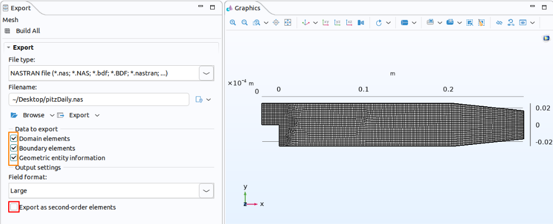
Figure 1. COMSOL export settings for the pitzDaily mesh, showing the Nastran file type, selected data, and second-order element option.
In the Data to export section, select domain elements, boundary elements and geometric entity information. The last one stores the surface or volume number of every element in the file, which is what lets you identify surfaces and volumes and assign them to physical groups in Gmsh. Finally, uncheck Export as second-order elements, so that the file contains first-order elements for the gmshToFoam conversion. Once everything is set, export the .nas file. It is ready for the Gmsh session.
Note: check the boxes below and the checklist shows whether the file will work.
Are your export settings correct?
Why does the second-order mesh look like? Toggle the element order to see differences.
First order vs. second order
| Element | First order | Second order |
|---|---|---|
| Triangle | 3 nodes | 6 nodes |
| Tetrahedron | 4 nodes | 10 nodes |
| Prism | 6 nodes | 15 nodes |
Filled dots are corner nodes, open dots are the extra midside nodes. Counts for the other element shapes depend on the element family.
gmshToFoam reads. With no midside nodes, a curved edge becomes a straight line between its corners, which is negligible on a fine mesh.gmshToFoam does not read these element types. It prints Unhandled element and skips them, so you can end up with only a fraction of your cells.2. Converting the mesh to Gmsh
Open the exported .nas file in Gmsh, then:
- Name the boundaries. Go to Geometry → Physical groups → Add and select Surface. In the physical group window, name each boundary group and assign the corresponding surfaces to it. The physical-group definitions are saved in a
.geofile. Note that surfaces left unassigned will appear underdefaultFacesafter conversion to the OpenFOAM mesh. - Name the volumes. Repeat the process with Geometry → Physical groups → Add → Volume, and assign a label to each domain.
- Mesh module. Under Mesh → Define, select 3D and, if desired, Optimize 3D.
- Export. Go to File → Export, select Mesh – Gmsh MSH from the drop-down menu, and choose Version 2 ASCII in the export window.
The resulting .msh file can be imported into OpenFOAM with gmshToFoam. Figure 2 shows the Gmsh session, with the physical-group and mesh menus highlighted.
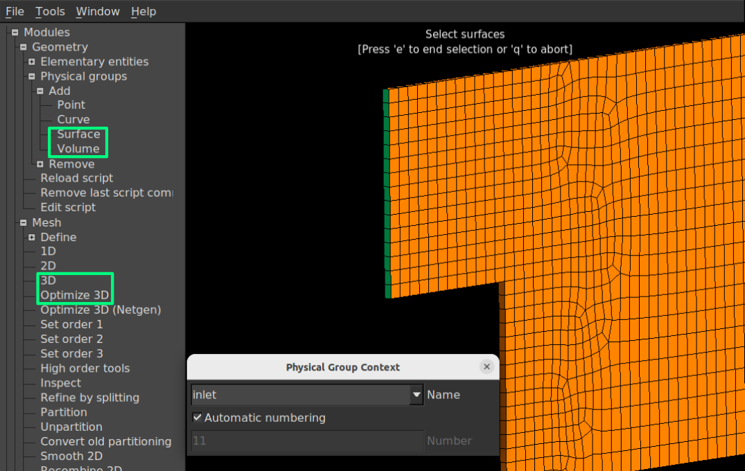
Figure 2. Boundary selection for the pitzDaily mesh in Gmsh, the physical-group and mesh menus are highlighted in the sidebar.
About Optimize 3D. It only works on tetrahedra and it changes the mesh you generated in COMSOL. Skip it unless you need it, and compare checkMesh before and after if you use it.
Why MSH version 2, and why ASCII?
Newer Gmsh versions write MSH version 4 by default, but gmshToFoam expects the older version 2 ASCII format. If the converter complains about the file, check the version in the export window first.
3. Importing the mesh to OpenFOAM
The next step is to convert the .msh file with gmshToFoam. Place the file in the OpenFOAM case directory, which should contain the system and constant folders, and run:
gmshToFoam mesh.msh
Replace mesh.msh with the name of your exported file. The conversion creates the mesh in constant/polyMesh. Afterwards, inspect constant/polyMesh/boundary: the imported patches may carry the generic patch type and need to be changed manually where another type, such as symmetryPlane or empty, is required. Panel below shows common boundary types and corresponding modification plus some relevant information.
Note: Cyclic boundaries need additional preparation. The paired surfaces require identical meshes in COMSOL, followed by patch configuration in OpenFOAM with the
createPatchutility and acreatePatchDict.
Common boundary types
In constant/polyMesh/boundary, set:
4. Checking the mesh
Run the standard check and visualize the result in ParaView:
checkMesh
touch case.foam   # then open case.foam in ParaView
Compare the cell count with the mesh statistics in COMSOL, and look at the patch names in the boundary file. If something looks off, these are the usual errors:
gmshToFoam prints "Unhandled element" and I have far fewer cells than in COMSOL
The export contained second-order elements, which gmshToFoam skips. Export again with Export as second-order elements unchecked (see step 1).
Some faces ended up in defaultFaces
Those surfaces were not assigned to any physical group in Gmsh. Add them to a group and export the .msh again.
All my patches have the generic type "patch"
That is expected: gmshToFoam does not know what a surface is for. Set walls, symmetry planes and empty patches by hand, as in the patch-type picker above.
My cyclic patches do not match
The two paired surfaces need identical meshes. Make sure they are meshed identically in COMSOL (for example by copying the mesh from one face to the other) and then configure the pair with createPatch.
Automated Gmsh script
Naming surfaces by clicking through the Gmsh GUI can be automated, especially when the geometry changes and you re-export the mesh again. So I wrote a Python tool/script that does the conversion and the naming from the terminal. It:
- converts the
.nasmesh to first-order elements and checks thatgmshToFoamcan read every element type, - lets you name surfaces and volumes at a prompt, with an optional Gmsh window that shows the surface numbers while you type,
- writes the MSH 2.2 file, reads it back and checks the groups and element counts before putting it in place,
- stores the boundaries and their bounding boxes in a small JSON file, so a re-export of the same model can be done fast (
--groups).
pip install gmsh
python nas_to_msh.py pitzDaily.nas
gmshToFoam pitzDaily_named.msh
Re-exported the mesh with a different element size? Reuse the names:
python nas_to_msh.py pitzDaily.nas --groups pitzDaily_groups.json
The script asks for a group name and the surface numbers that belong to it. Try the naming step here. The pitzDaily mesh has 10 surfaces, and the box below shows what the tool would write into the $PhysicalNames section of the .msh. Prefer to see a whole run first? Step through a complete session below. The mesh sizes and bounding boxes are illustrative values, the output format is the real one.
Different steps of a session
If you use it, I would be glad to hear how it works on your meshes. Issues and suggestions are welcome in the repository.